3 Assembly & Setup
3.1 Requirements
The Thor (RO3) robot has the following utilities requirements:
| Utility | Requirement |
|---|---|
| Electrical | 90 ~ 264VAC, 47-63Hz, 15 A maximum at 120VAC. *see note below for pre-production units |
| Internet | Wi-Fi or RJ45 (Ethernet) wired connection for remote updates and support. |
| Floor | Mount to a structurally sound concrete floor or engineered base per local codes |
**Pre-Production Unit Note: For full speed / payload, need a 220VAC power source. We are shipping with 110V boxes now, which limits speeds. Nominal power draw at full speed / payload is <4kW. Future control boxes can be ypdated
3.2 Lifting the Thor
Thor is a heavy industrial machine component and must be moved using proper lifting equipment and safe handling practices. The Thor arm assembly weighs approximately 79 kg (174 lb) including cable, so it should not be manually lifted; instead, use a hoist, crane, or forklift rated for the load and use appropriately rated rigging. Before lifting, ensure the arm is powered off, any end effector and payload are removed, and the work area is clear so the load can be controlled without people entering the path of the lift. Attach lifting straps only at the approved strap location shown (around the upper arm / shoulder–elbow area) and keep all lifting forces off the wrist, tool flange, covers, and cables.
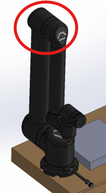
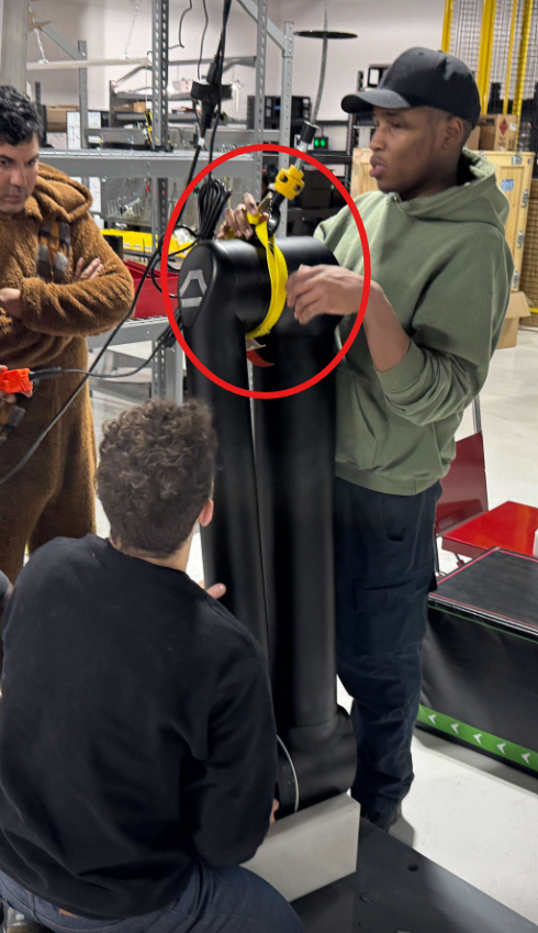
Lift slowly and smoothly to prevent swinging or rotation, keep the load as low as practical during transport, and use a spotter or tag line as needed to guide the arm into position. If the lift or placement cannot be completed safely with available equipment, stop and contact Standard Bots Support or your facility’s qualified rigging personnel before proceeding.
Lifting and positioning must be performed by qualified personnel trained in industrial rigging practices
3.3 Assembly Procedure
3.3.1 Overview
This procedure describes how to anchor the Thor pedestal base to a concrete floor and mount the Thor robot arm. Follow the steps in order. Do not power the robot until all mechanical fasteners are installed and torqued.
3.3.1.1 Example Installation Reference (Installer to Verify)
These values are intentionally conservative and industry-standard. They are suitable as a starting point. Anchor type, embedment depth, torque values, and installation details are provided as general reference only. Final anchor selection and installation must be verified by the installer based on site conditions, local codes, and anchor manufacturer specifications
3.3.1.2 Anchor Type
Type: Mechanical wedge anchor
Diameter: M16 (5/8 in acceptable equivalent)
Minimum embedment: 125 mm (5 in)
Concrete: Normal-weight concrete, ≥ 25 MPa (≈ 3,600 psi)
Final torque: Torque per anchor manufacturer spec
3.3.1.3 Required Tools and Equipment
- Rotary hammer drill
- Ø 16 mm (5/8 in) concrete drill bit
- Vacuum and blow-out bulb (or compressed air)
- Torque wrench capable of 150 N·m
- Hoist, crane, or forklift rated ≥ 250 kg
- Steel shims
- Standard metric socket set
- PPE (eye protection, hearing protection, gloves)
3.3.1.4 Pedestal Anchor Pattern and Orientation
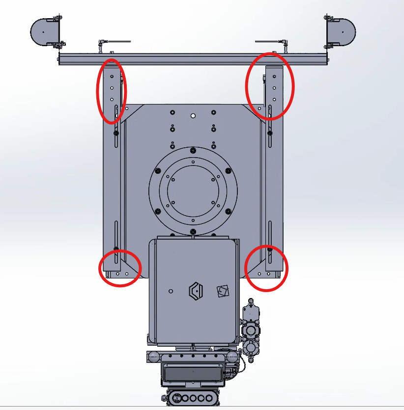
The Thor pedestal is secured using four anchor points, located at the four vertical corner gussets of the pedestal base.
These anchor locations correspond to the circled areas shown in the pedestal mounting image:
- Two anchor points at the upper left and upper right gussets
- Two anchor points at the lower left and lower right gussets
Each gusset includes a vertical slot, allowing minor adjustment during leveling.
If you are not trained in anchoring/rigger work, stop and use a qualified installer.
3.3.1.5 Step 1: Position and Mark Anchor Holes
- Place the pedestal in its final intended location.
- Orient the pedestal so the robot working envelope, cable exit, and service access are correct.
- Using the pedestal base slots, mark the four anchor hole locations on the concrete.
- Remove the pedestal and verify all marks are square and aligned.
3.3.1.6 Step 2: Drill and Clean Anchor Holes
- Drill four holes:
- Diameter: 16 mm (5/8 in)
- Depth: ≥ 140 mm (5.5 in) to ensure full embedment
- Clean each hole thoroughly:
- Vacuum dust
- Blow out debris
- Repeat until clean
Proper hole cleaning is required to achieve rated anchor performance
3.3.1.7 Step 3: Install Anchors and Set Pedestal
- Insert wedge anchors into each hole until seated.
- Place the pedestal back over the anchors.
- Install washers and nuts finger-tight only.
3.3.1.8 Step 4: Level the Pedestal
- Check level in both X and Y directions.
- Insert steel shims at anchor locations as required.
- Adjust until pedestal is level within acceptable tolerance.
3.3.1.9 Step 5: Torque Anchors
- Torque anchors in a cross pattern:
- Upper left → lower right → upper right → lower left
- Torque all fasteners per the provided installation drawing or fastener kit specification
3.3.1.10 Step 6: Prepare Cable Routing
Before mounting the robot:
- Verify the robot cable path is clear through or alongside the pedestal.
- Ensure cables will not be pinched between the robot base and pedestal.
- Confirm sufficient slack for full joint motion.
3.3.1.11 Step 7: Mount Thor Robot to Pedestal
Using lifting equipment:
- Lift Thor using approved lifting method.
- Lower the robot vertically onto the pedestal mounting surface.
- Align bolt holes fully before installing hardware.
3.3.1.11.1 Thor-to-Pedestal Fasteners
- Bolt size: M12 × 35mm
- Quantity: 6 bolts
- Washers: Hardened flat washers
- Final Recommended torque: 165 N·m (155 ft-lb)
- Install all bolts finger-tight.
- Torque in a cross/star pattern to final torque.
3.3.1.12 Step 8 — Secure Cables and Strain Relief
- Connect robot power/data cable.
- Install strain relief so connectors are not load-bearing.
- Verify cables have adequate slack and clearance.
3.4 Final Mechanical Checklist
Before power-on, verify:
- All fasteners torqued per provided installation drawing or fastener kit spec
- Pedestal level confirmed
- Robot mounting bolts installed and torqued per provided installation documentation
- Cables routed and strain-relieved
- No tools or debris remain on pedestal
3.5 Connecting Control Box
To connect and mount the control box on the base:
- Set the control box on the pedestal mounting plate in the same
orientation as the screenshot.
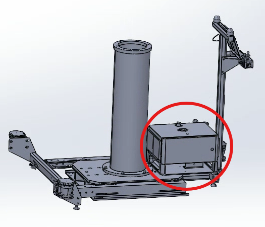
- Seat & secure the box to the plate with the pedestal mounting bolts (use your site hardware). Tighten evenly.
- Route the control-box output cables through the pedestal cable route/gland toward the pedestal pillar; secure with ties so they are strain-relieved.
- Connect the arm power/data cable to the port labeled Arm Data + Power
- Connect Ethernet if required
- Connect AC mains
- Service / USB: plug the service USB-C and any maintenance leads into the control box; secure and tuck the cables
- Verify E-Stop is released; power on; Confirm the control box indicates normal operation with no active faults
3.5.1 Quick checks
- Earth/ground connected and visible at chassis ground.
- Cables are strain-relieved and not pinched.
- Verify the control box indicates normal operation before enabling motion
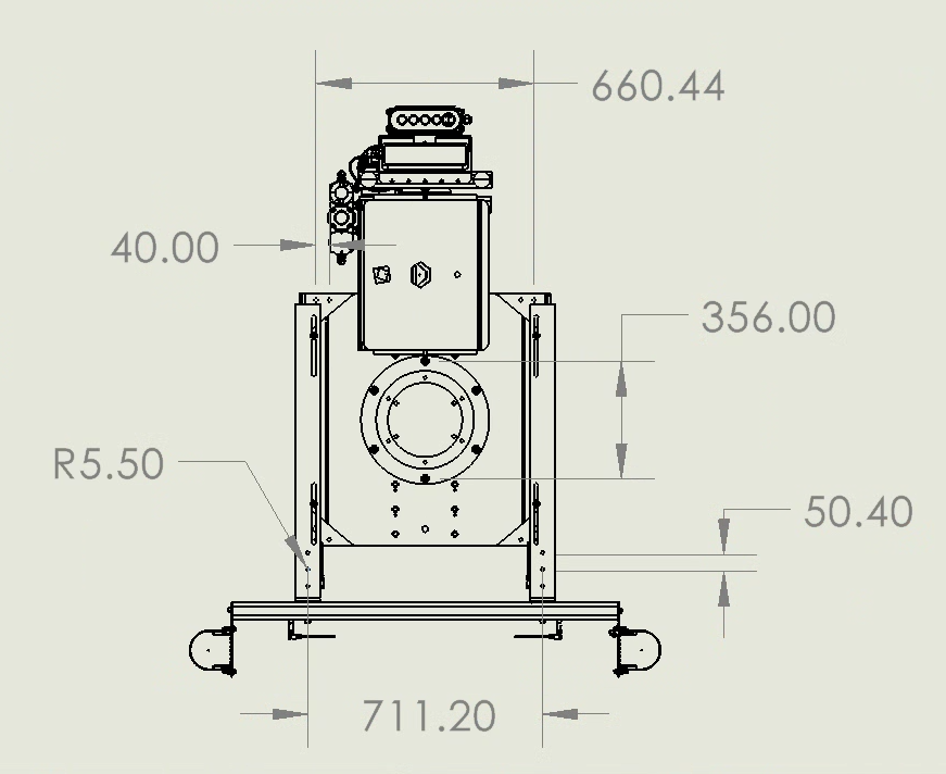
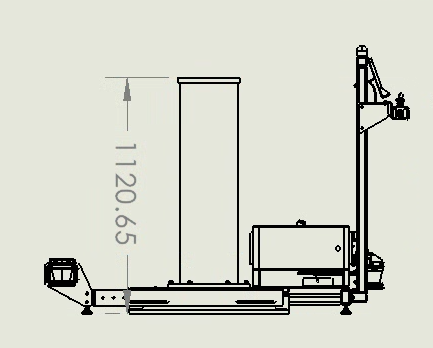
3.5.2 Base Drawings:
3.6 Setting up Tablet
The included iPad is used to configure, control, and program the RO3. Here’s how to get it set up:
Take the iPad out of the box and turn it on.
If prompted at any point, enter the default passcode of “0000”.
Open the “Settings” app on the iPad, then configure your network. If you are using Wi-Fi, there is a “Wi-Fi” section. If you are using an Ethernet adapter, an additional option to configure Ethernet should appear in the right sidebar.
- When connecting your robot to Wi-Fi, please make sure that it does not require to go through a splash-page to access.
Navigate to the home screen (by pressing the bottom button, if the iPad has one, or swiping up from the bottom, if it doesn’t). Open the Standard Bots app.
Open the Standard Bots app.

You will be brought to the home screen of the Standard Bots app. Here you will see three blocks. The top right named Docs will bring you to the Standard Bots manual. The bottom right block, named Support, will bring you to a tab that shows how to reach Standard Bots support line. It shows the support email, the support phone number, as well as the address of Standard Bots office. The large block on the left is where you will go to add your new robot.
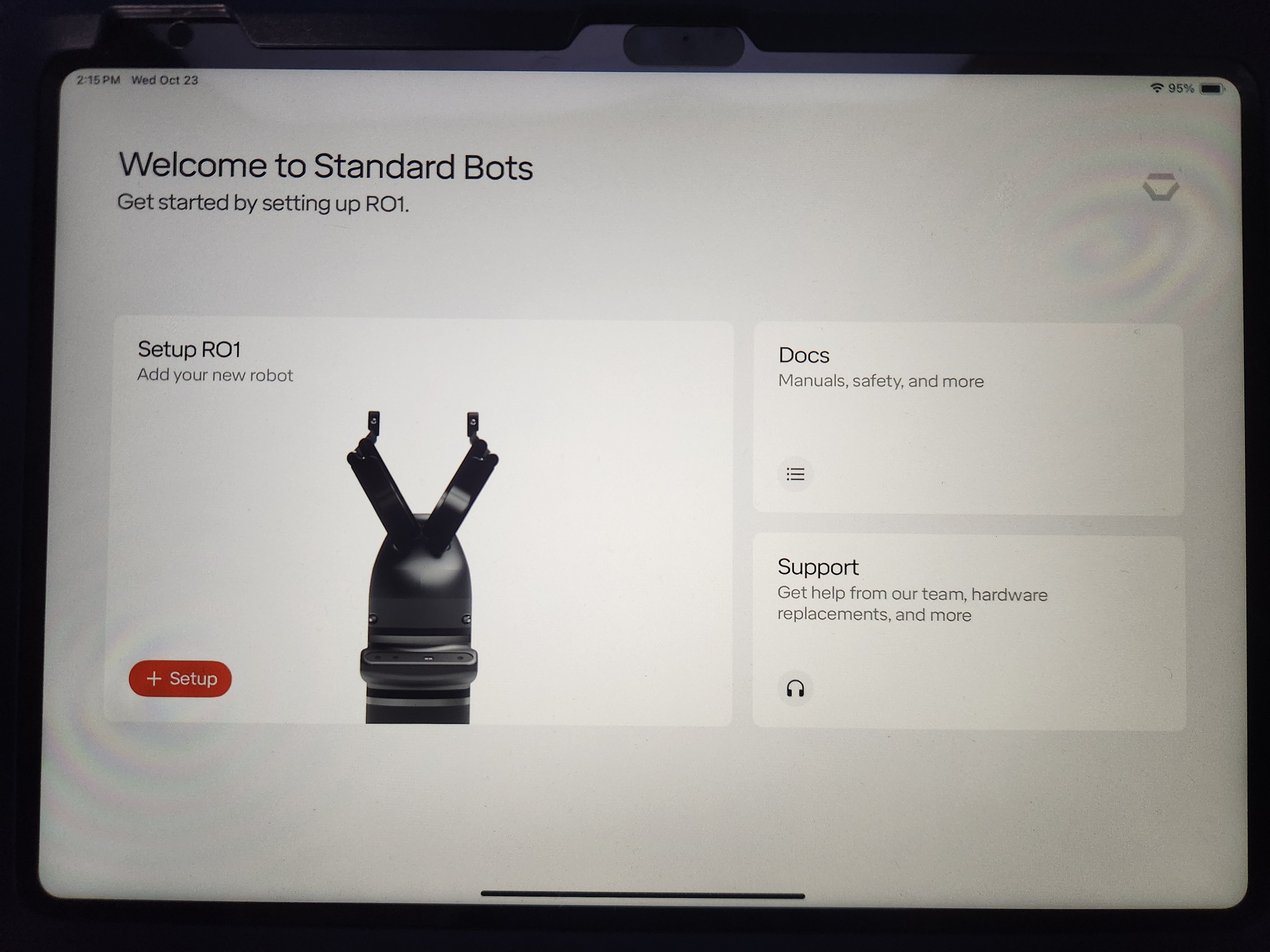
Tap “+Setup” on the home screen.
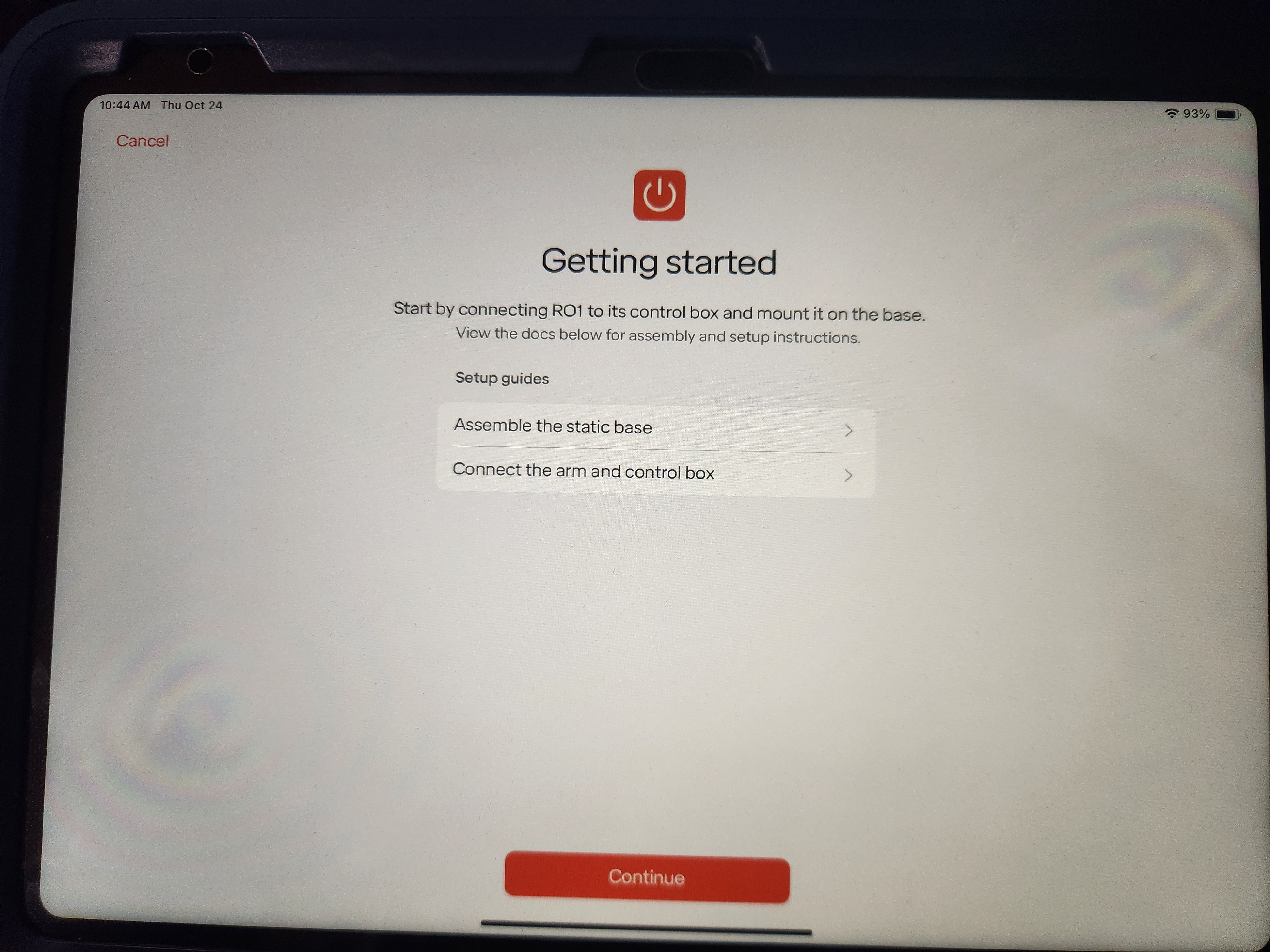
You will be brought to the Getting Started page. Here you can also find guides for how to assemble the robot base as well as how to establish connection between the robot arm and the control box. Once ready, press the Continue button
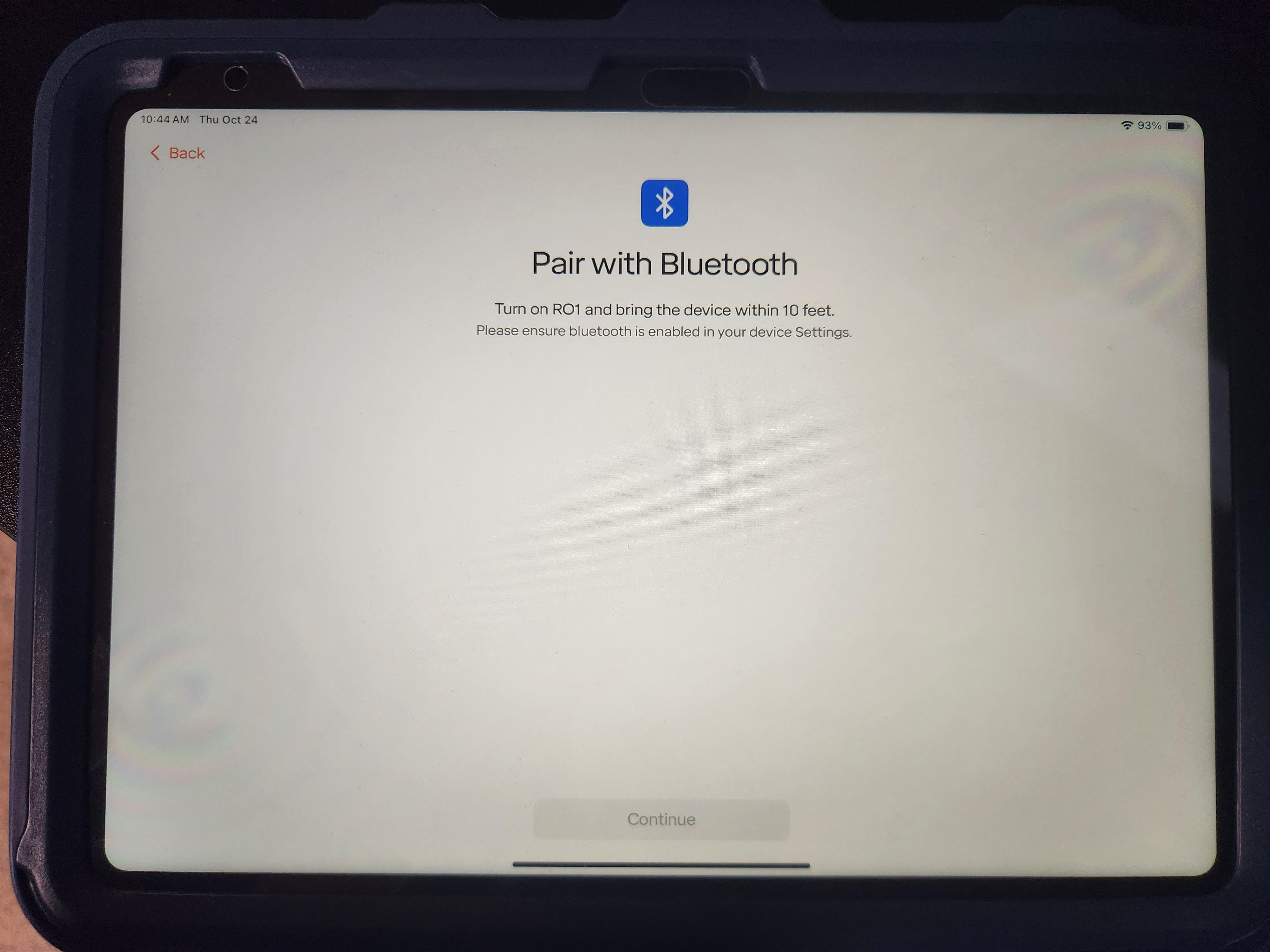
The Pair with Bluetooth page will appear where the iPad will search for the robot over Bluetooth. Make sure the Thor is turned on and has the included antennae screwed on. Once the Thor shows up, choose it from the list and proceed.
The app will ask you to enter your network credentials again. You can configure the robot to connect over Wi-Fi or Ethernet, regardless of how your tablet is connected.
The app will also walk you through setting a PIN and choosing a name for your Thor.
After setup is completed, you can connect to your bot.
Once connect you can reset the estop (if required), unbrake, and begin jogging the robot. Refer to Section 5 for more details on operating the robot and constructing routines.
3.7 Unmounting & Transporting
3.7.1 Warnings
- Do not attempt to move the arm while it has power
- Do not force the robot into a position while power is off, doing so may damage the robot.
- Only lift the Thor arm with approved equipment mentioned earlier in document
3.7.2 Before transportation:
- Ensure the robot is in the desired position for
transportation.
- If needed, the robot can be put into the position required for the
original box by:
- Navigating to the Move Robot view
- Go to the Robot menu in the upper right
- Select “Settings”
- Select “Box Robot”
- Save and confirm the Payload
- Click and hold down the “Move Live Arm To Visualizer Position” button. The robot will move into the packing pose.
- Click the hexagon button in the bottom right of the Move Robot view
- Select “Brake Robot”
- Unplug the control box from the AC power source
- Wait 30 seconds for stored power to dissipate
- Unplug the connector between the arm and robot buy twisting the locking mechanism and pulling down on each end
- Disconnect any inputs and outputs from the control box
The Thor control box has an integrated handle for ease of transportation. Ensure all cables are disconnected from the Thor control box before moving or shipping the control box. Ensure Thor control box is well packaged, preferable in the original packaging, before shipping the Thor control box.
3.7.3 Unmounting the Arm From the Pedestal — Thor
Thor is a permanently mounted industrial robot and is not intended for routine removal by end users. Removal of the robot from the pedestal or base requires appropriate lifting equipment, trained personnel, and adherence to site-specific safety procedures.
For robot relocation, servicing, or shipment:
- Power the system down and disconnect all electrical connections.
- Remove any attached tooling or payloads.
- Secure the robot to prevent unintended motion.
- Use only approved lifting methods and original packaging where available. Please reference Section 3.2, “Lifting The Thor”.
For assistance with removal, crating, or transport, contact Standard Bots Support before proceeding.
3.8 Connecting End Effectors
3.8.1 Mechanical Connection
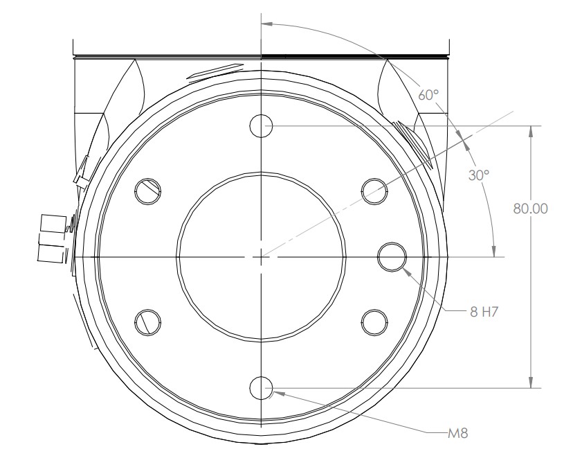
The Thor robot uses a modified version of the standard ISO 9409-1-80-6-M8 80 mm ISO robot flange pattern. The flange connector offers four locations for the locating pin, where the ISO 9409-1-80-6-M8 standard offers 1 pin location. Any tool that follows the standard 80mm pattern will mount to the Thor robot flange. A diagram of the mounting pattern is shown below.
3.8.2 Fully Integrated Tools
Standard Bots supports full integration with the following tools. These tools can be fully controlled using standard instructions in the Standard Bots Routine Editor. Other tools can be controlled via digital IO.
- DH Robotics AG-105-145 Linkage Tool
- DH Robotics CGI-100-170 Centric Tool
- DH Robotics PGC-300-60 Parallel Tool
- Onrobot 2FG7 Parallel Tool
- Onrobot 2FG14 Parallel Tool
- Onrobot 3FG15 3 Finger Centric Tool
- Onrobot Dual Changer
- Schunk EGU
- Schnunk EGK
Follow the instructions provided with the tooling to connect the tooling to the robot flange, and connect the wire to the provided connector at the end of the robot arm.
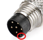
Be careful when attaching the m8 tool connector. Ensure that you line up the key with the receiver when you plug it in. Do not twist it, the pins are fragile and this can cause the pins to break.
3.8.3 Other Supported Tools
In addition to the above tools, Standard Bots generally supports most tools that mount to the 80mm flange and that support 24VDC discrete control. Please contact Standard Bots support for assistance with confirming tooling compatibility.
3.9 Control Box Inputs and Outputs
3.9.1 Digital Inputs and Outputs
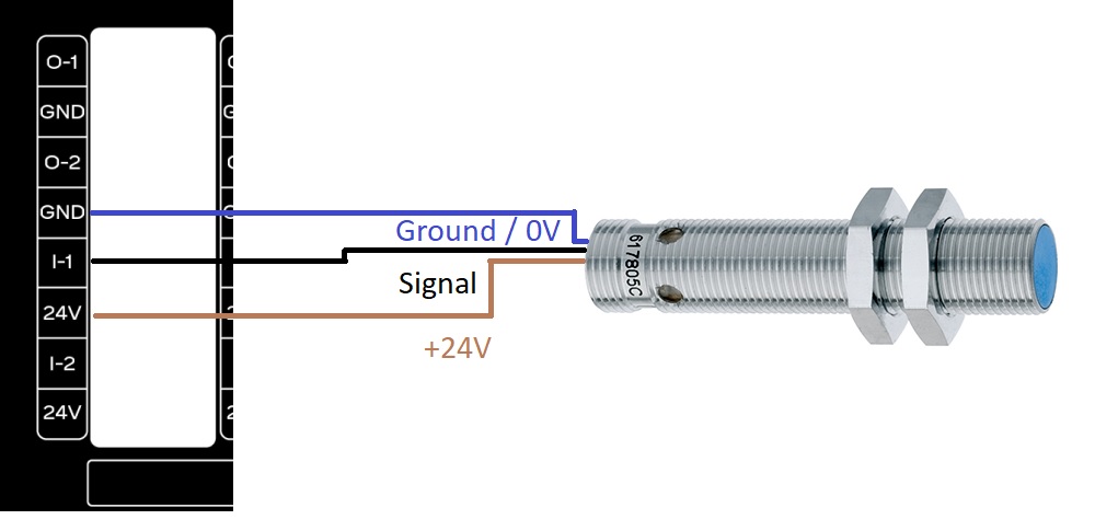
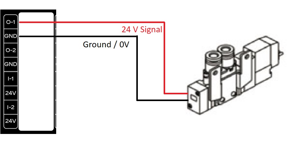
The Thor control box supports 16 24VDC digital inputs and 16 24VDC digital outputs. The signals are sourcing or PNP. The digital outputs support up to 0.7 amps of output, for larger capacity use the digital outputs from the robot to drive a relay coil to a separate power source.
Example of wiring a proximity sensor into the RO1 control box:
Example of wiring a pneumatic valve into the RO1 control box:
3.9.2 Analog Inputs and Outputs
The Thor control box has 4 analog outputs and 2 analog inputs available on the control box. These are currently unsupported.
3.9.3 I/O Power Select Feature
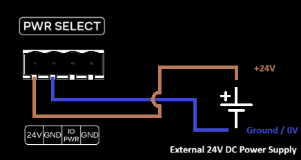
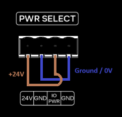
The Thor control box enables users to manage input/output (I/O) functions using its integrated 24V power supply. Alternatively, an external 24V power supply can be used if preferred. The diagrams below illustrate both wiring configurations.
3.9.3.1 Integrated 24V Power Supply
The image below illustrates the wiring configuration for utilizing the integrated 24V power supply for I/O functionality.
3.9.3.2 External 24V Power Supply
The image below illustrates the wiring configuration for utilizing an external 24V power supply for I/O functionality.